OPFORGE ICS Scenario 01: Silent Tank Overfill (Implementation)
This document provides the technical implementation of the Silent Tank Overfill scenario.
For the conceptual overview and motivation:
Purpose
The goal of this scenario is to answer a specific question:
Can a defensive system detect when a control-plane change causes a meaningful change in physical process behavior?
This scenario measures impact, not just alerts.
Architecture Overview
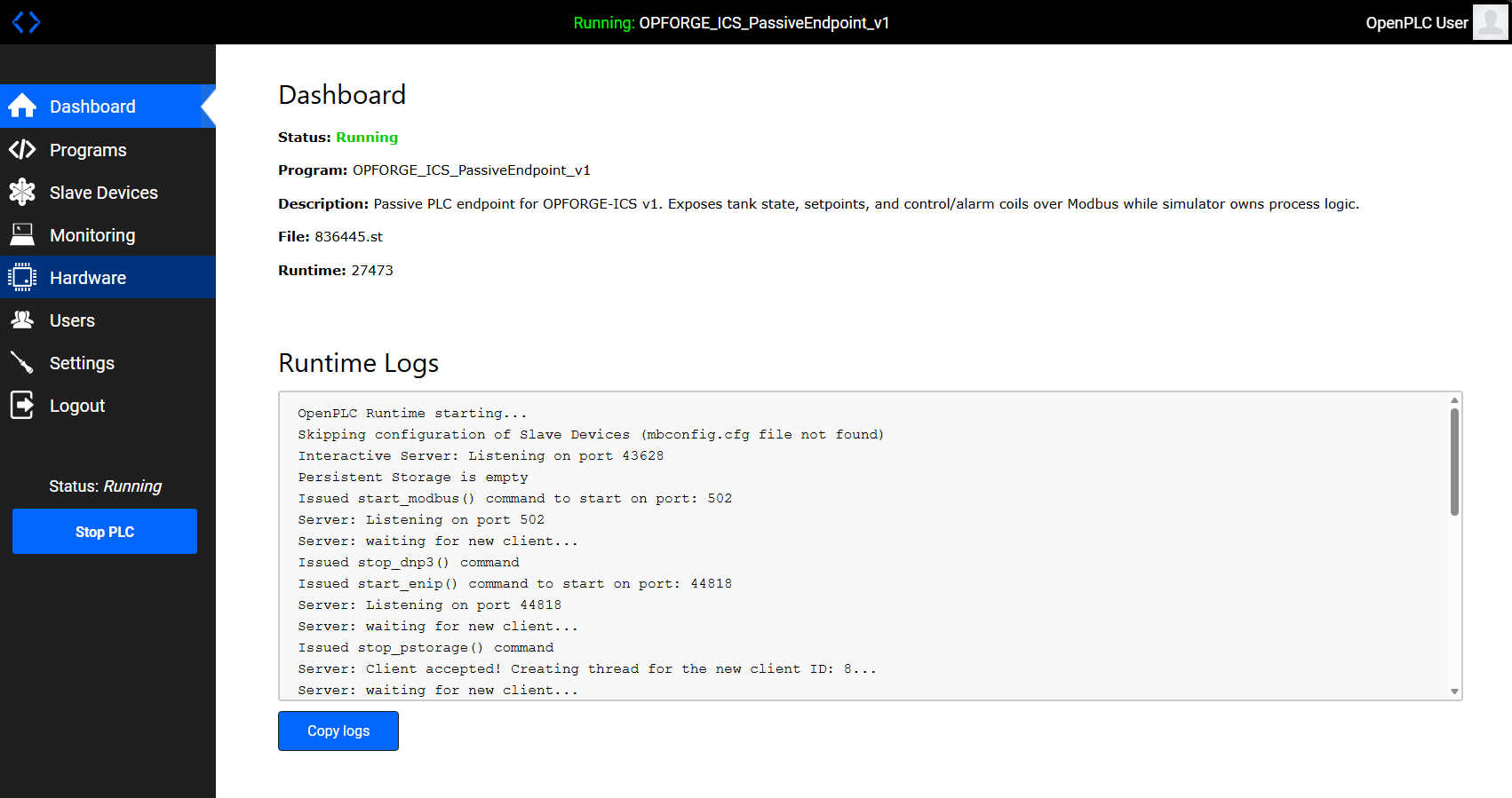
OpenPLC exposes control state over Modbus while the simulator enforces process behavior.
The environment is intentionally minimal:
- OpenPLC (
opf-plc01) - exposes registers and coils over Modbus TCP (port 502) - Process Simulator (
opf-sim01) - implements tank physics, control logic, and alarm behavior - Modbus TCP - serves as the control-plane interface
- Attack Scripts - perform direct register manipulation
The PLC exposes state. The simulator enforces reality.
Register and Coil Design
Holding Registers
R0 = tank_level
R1 = low_setpoint
R2 = high_setpoint
R3 = high_high_setpoint
Coils
C0 = inlet_valve
C1 = low_alarm
C2 = low_low_alarm
C3 = high_alarm
C4 = high_high_alarm
Baseline Behavior
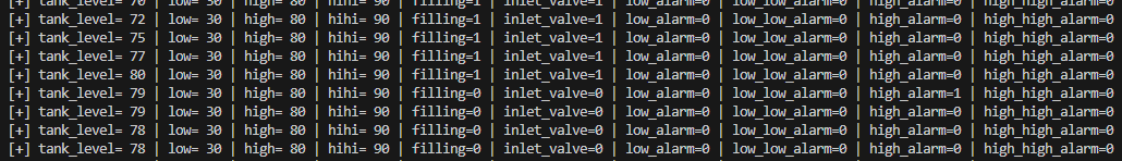
The system operates using hysteresis control:
- If
tank_level <= low_setpoint→ fill - If
tank_level >= high_setpoint→ stop filling
Operating band:
30 → 80 → 30 → repeat
Alarm behavior:
low_alarmat ≤ 30low_low_alarmat ≤ 10high_alarmat ≥ 80high_high_alarmat ≥ 90
Under baseline conditions:
- alarm ordering is consistent
- system behavior is predictable
Attack Implementation
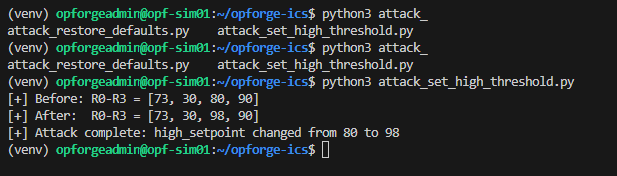
A single Modbus write modifies the high setpoint:
R2 (high_setpoint): 80 → 98
Execution:
python3 attack_set_high_threshold.py
This is a control-plane action, not an exploit.
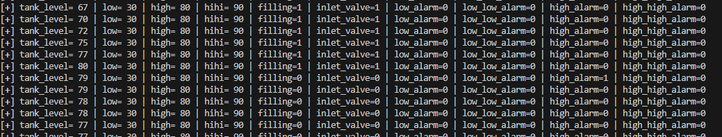
Post-Attack Behavior
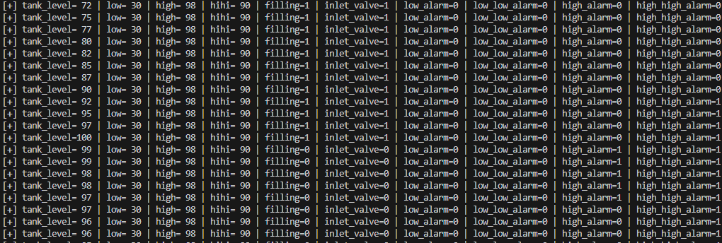
The system enters an invalid state:
high_high_alarm = 1whilehigh_alarm = 0
Invariant violated: high_high_alarm should never trigger before high_alarm
Observed effects:
- extended fill duration
- delayed
high_alarm high_high_alarmtriggers first
This represents a process integrity failure, not a network anomaly.
What Should Be Detected
A capable detection system should identify:
- Modbus write to critical register
R2 - deviation from expected setpoint baseline
- abnormal alarm sequencing
- process behavior outside normal operating bounds
Recovery
Restoring the original setpoint returns the system to expected behavior, confirming the impact was caused by control-plane manipulation.
Reproducibility
Baseline:
python3 plc_init.py
python3 -u tank_sim.py
Attack:
python3 attack_set_high_threshold.py
Restore:
python3 attack_restore_defaults.py
High-state validation:
INITIAL_TANK_LEVEL=95 python3 -u tank_sim.py
Key Insight
The critical signal is not the write. The critical signal is that the system is no longer behaving correctly.
Next Steps
- integrate telemetry into detection pipelines
- score detection vs physical impact
- expand to additional scenarios:
- loss of view
- actuator manipulation
- false data injection
Closing
A detection that fires is not sufficient.
A detection that demonstrates the system remains within safe operating bounds is.
That is the standard OPFORGE is designed to test.